Work
Design Layout: (Basic Layout On Left)
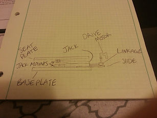
The car jack will be placed between two plates, the seat plate and base plate. Each plate will be mounted to the jack with a pin between two beafy angles. When driving the jack to lift the seat, with the jack oriented appropriate to the design, the drive worm extends outward as well as changes its angle mirroring the seat's angle. This change in agle causes the application point for the drive imput to move down away from the user as their seat moves upward. To eliminate this problem it was necessary to flip the jack upside down, opposite to the proper lifting orientation. The mounts from the base plate to the jack provided the stability needed, that would not be provided by the jack alone when upside down. As you can see in this simple sketch the left, there are two more components, the slide and linkage. The slide would have provided support for the ninety degree bevel gear corner joint (linkage), which was in the orginal design for comfortability. However, these two components were eliminated due to the extremely expensive cost and no importance to the functionality of the device.
Parameters of Analysis:
There are four main theoretical equations used for the analysis on this device. The following four equations were prominant; Max bending stress = Mc/I, Max tensile and compression stress = F/A, Torque = F x D, and Beam Deflection = -PL^3/3EI (deflection formulas will vary due to the situation at hand).
Static loading analysis was conducted on each component of the 'Seat Jack' to choose a material that would be suitable to support a 276 lb test dummy (Weight of test dummy use by General Motors today), be as light and inexpensive as possible, all while complying with a safety factor of five. Analysis and cost guided the decision to use one material for all parts fabricated. The material of choice was to use 6061 T-6 aluminum. By keeping all the materials the same, price was reduced dramatically. This aluminum was able to comply with the safety factor and suport our test specimen all with only allowing a maximum deflection of less than two hundredths of an inch.


Manufacturing Process:
During the manufacturing stages changes were expected and did occur. Due to the limited access to the universities CNC mills and lathes, the computer numerically controlled steps were changed to manual machining processes. Although this took more time actually machining parts, it took less time preparing for the processes and allowed for a more adaptable approach that could not be performed on some CNC machines. Fitting the pins through the jack and into the mounts is a prime example. Getting the exact snug fit desired on a CNC machine would have used a more trial and error approach, which would have worked but would have been more cost defective throwing away trials that did not come out to desired expectations. On the other hand, positioning the holes for the mounting screw which hold the mounts to the inside of each plate would have been much easier with a CNC machine. So there are trade offs in both directions but in the long run I am glad I machined my parts manually.
Other changes include; the omittion of the slide and corner gear box, addition of a support and guide track, as well as fabricating the mounts to be larger to provide more strength to the supporting pins.
Testing Method and Results:
Trial tests as well as measurements were conducted to ensure that design requirements as well as desired specs were satisfied. Trial tests were conducted to find cycle time for range of movement and the torque required to lift different weighted specimens. Measurements were taken to find out the weight, angle and range of motion, and overall size.
Desired specs and requirements were attainable with the design suggested. Having an average cycle time of 24.6 seconds met the requirement of being under 30 seconds. Torque required at different specimen weights is still in need of conducting. Overall weight was under by three and a half pounds. The range of motion ended up being much greater than the desired thirty degrees, coming in at nearly ninety degrees providing thirteen inches of lift.
